


d3v
SRK
For those with the Battle Edition who would prefer the feel of a Seimitsu LS-32 (smaller deadzone, slightly stiffer) than that of the Qanba JLF knock-off (or a Sanwa JLF).
First up Read the other Injustice thread, I will wait.
http://forums.shoryuken.com/discussion/174669/injustice-gods-among-us-battle-edition-arcade-stick
Okay its time to Mod the Injustice Stick, as the Real Injustice is not because
Spoiler:
But that PDP decided to use Qanba made parts.
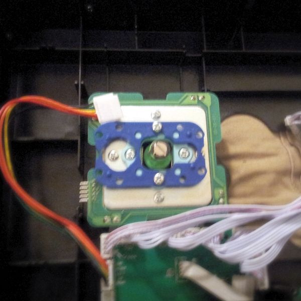
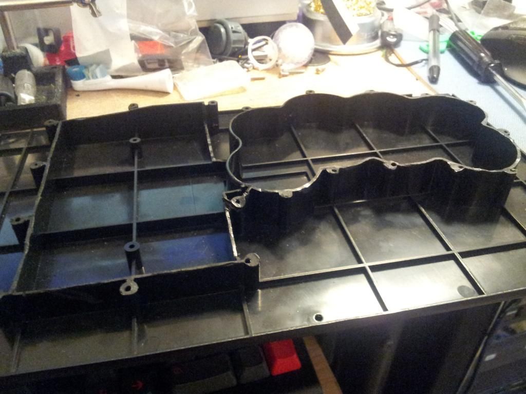
First what I did was attempt to fit a Seimitsu LS-32-1 (because Sanwa is poop and the stock Qanba parts are worst).
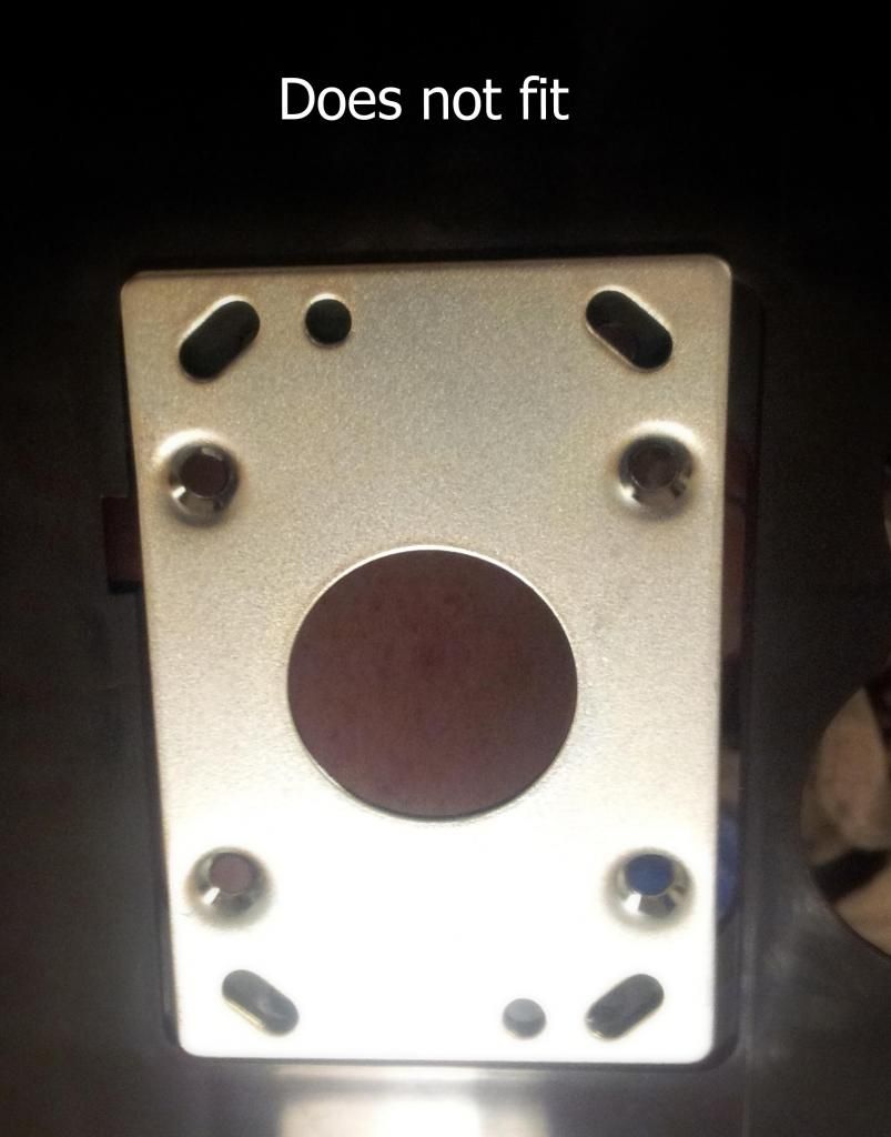
Unlike the Sanwa JLF mount plate, the Seimitsu mount plate doesn't fit in the gap provided. Protip: for you Sanwa lovers, you can swap the JLF's mount place for the stock mount place and your JLF mounts fine.
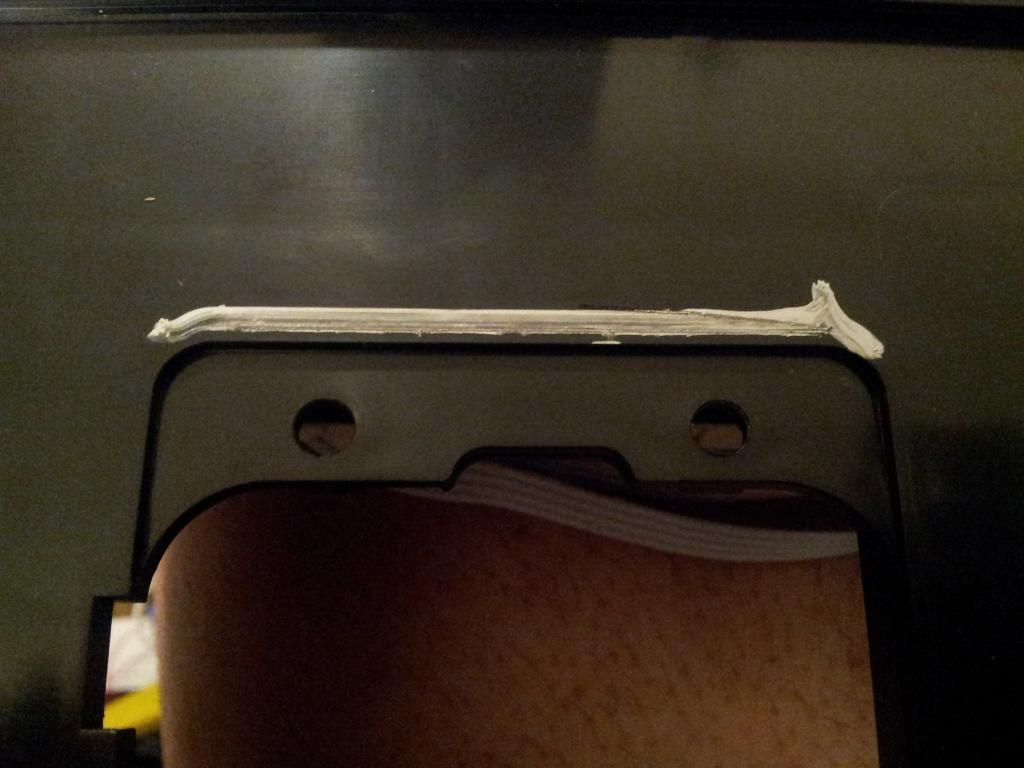
I marked off where to dremel
And made my Cuts. Like the JLF mount plate the LS-32 plate mount holes does not like up with the Injustice stick.
First remove the nuts that are going to hold the mount plate in place,
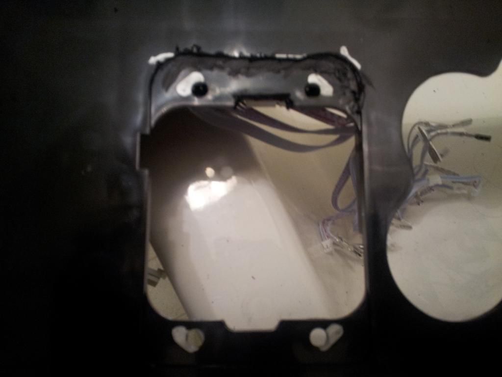
Then use a dremel or a drill to widen up those screw holes, and continue with cutting away those brackets that held the nut in place.
As you can [NOT] see I added some metal washers to reinforce those holes.
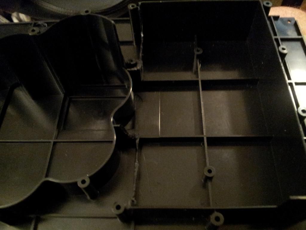
If you are stopping the Mod here, you want to mod the bottom lid as well so you can close your stick
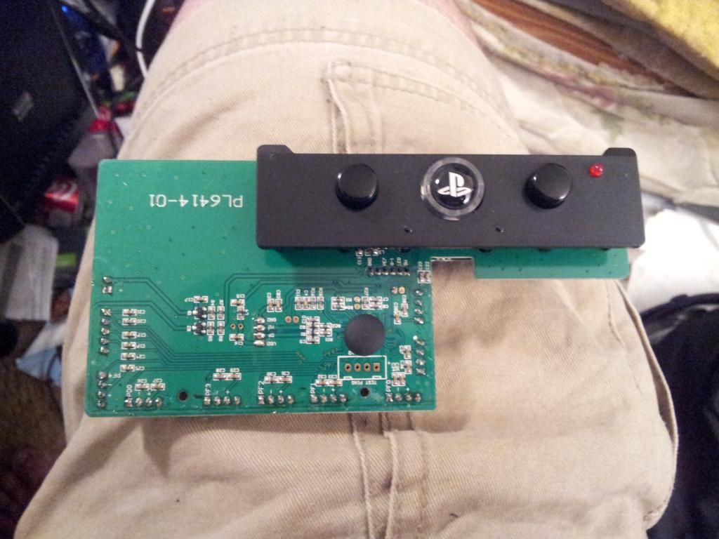
Next is hacking up that PCB.
Remove the side panels, so you can remove the rear panel (the one with the USB ports and switched) the front panel can stay.
Then you can remove the PCB assembly.
Take that apart, note the 2 ribbon cables, 1 is for the USB and the other is for the switches, go ahead and cut both ribbon cables. If you are a real Pro, desolder them.
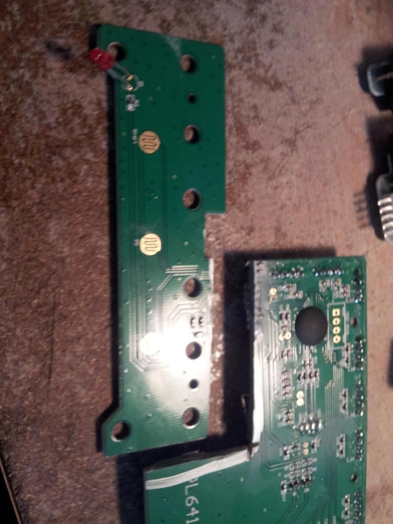
Then Cut your PCB up like this. Throw out the larger section as we no longer need it. Keep the USB daughter board.
This next part I forgot to take photos of so bear with me.
Note the daughter board with the switches and USB port. The spot the USB ribbon cable was is labeled. You can attach a USB cable (or just 4 wires) so you can run them to your new PCB.
Reference for USB hacking http://pinouts.ru/Slots/USB_pinout.shtml
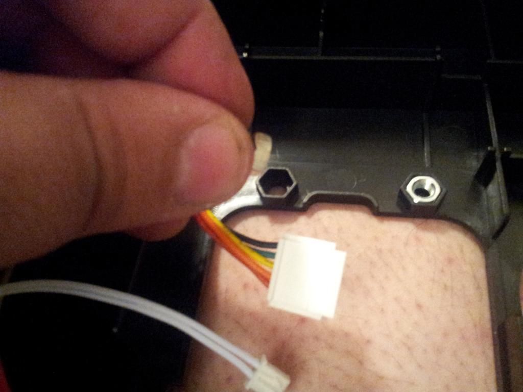
The only other useful point right now is the GND point where the other cable was.
Using some 30 awg wire I tapped the 4 signal trances for Start, Select, Home and Ground. That wire for ground was soldered to one of the 2 far poles (left or Right) for the tournament lock switch as the middle lead to that GND point.
This way I can still use the Tournament Lock. The remaining 30 awg wires where splice to thicker 24 awg wire which is leading to my PS360+ PCB.
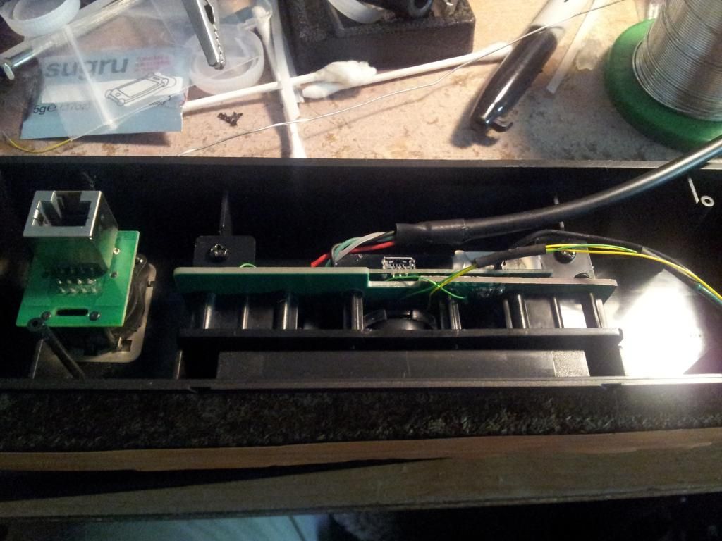
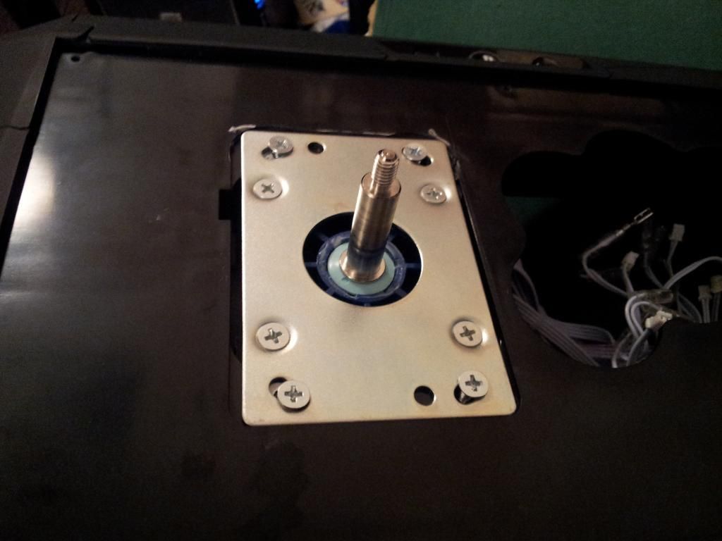
Once I drilled a 24mm hole and did some dremling so I can fit a Neutrik RJ45 Passthrough, and reassembled the remaining PCBs
So now the back of my rear panel looks like this.
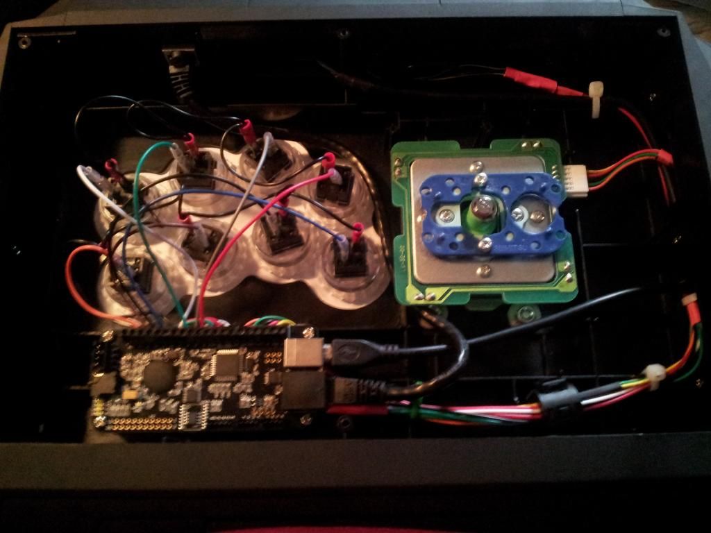
Attaching the rear panel back to the rest of the stick (and cutting a hole for the Neutrik to fit), then super gluing some standoffs into place my stick looks something like this.
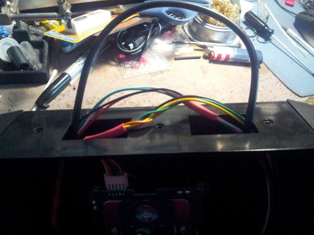
See how I routed the wires through the side openings? Normally bits of plastic on the side panels will prevent this.
A Dremel, hot knife, pliers or other means of cutting will make short work.
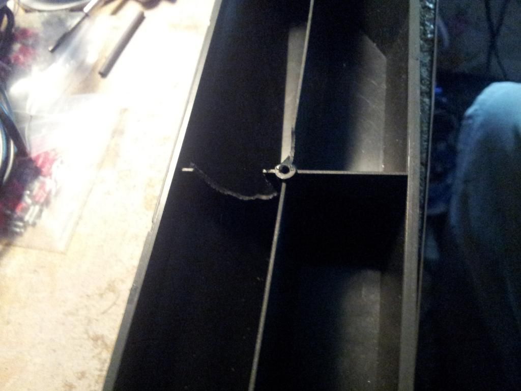
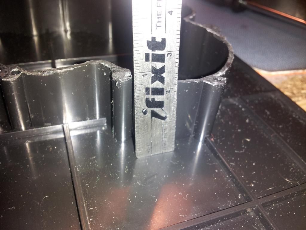
Now the final part, after replacing the sides, its time to close the lid. But wait there is a PS360+ and a LS-32 in the way.
So trim all that annoying plastic . Do not get rid of it, just cut it down to a half inch to a inch.
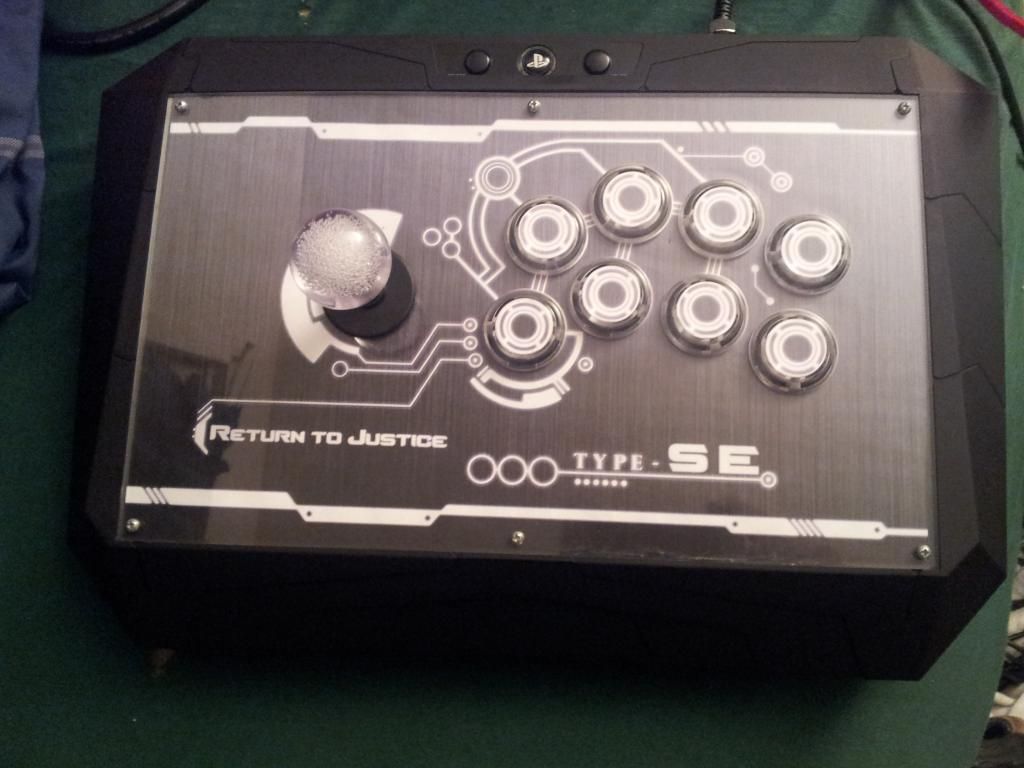
And here is the Final Product. Template courtesy of d3v.